In this case the tester automatically generates diagnostics information to point out what may have caused. To isolate the cause of strobe crosstalk run at full frame rate.
Next Near End Crosstalk Troubleshooting With Dsx Cableanalyzer Fluke Networks
If wires are not tightly twisted the result is Near End Crosstalk NEXT.

How to fix near end crosstalk. ULMB 85fps at 85Hz to reduce or eliminate the double-image effects when strobing on low frame rates. The peak far-end noise scales with the coupling length. Channel NEXT is the NEXT value measured between one wire pair and another in the.
The first thing to do in the event of a NEXT failure is to use the field tester to determine at which end the NEXT failure occurred. If layer two is running north to south then make sure that layer three is running east to west In this way you can minimize the possibility of broadside coupling. A via surrounded by a closed ground wall shortening the planes acts as an electrical boundary.
The pair causing the interference is called the disturbing pair while the pair experiencing the interference is the disturbed pair. Accuracy of the Near End Crosstalk NEXT measurements is 1 dB at 250 MHz and the worst case margin of a link at 250 MHz is 04 dB. What this really means is that one pair can interfere with another pair at the end that is doing the transmitting at the time.
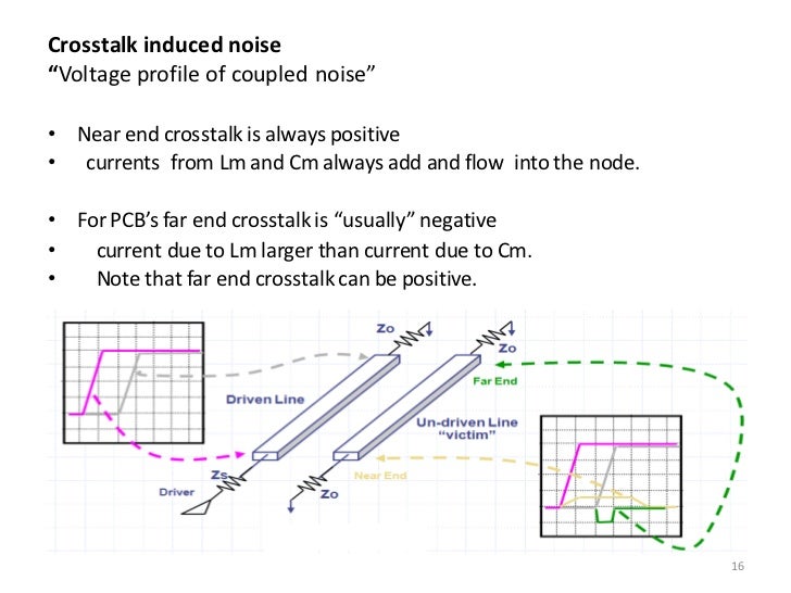
The backward cross talk or Near End Cross Talk NEXT is observed on the victim line at the end nearest to the driver line of the aggressor. Increase the separation between the traces. In reality the transmitting cable will interfere all the way down the cable to the other end but the interference will be the greatest at the end where the interfering signal is transmitted from called the Near end.
In the high-density PCB design complexity is impossible to completely avoid crosstalk but the designers in the system design should consider the case does not affect the performance of other systems choose the appropriate method to seek to minimize crosstalk. Reduce the length for which the trace couple. Some of the ways it does it is by twisting the wires together and creating more space between the wires.
To guard against this balanced twisted pair cable has been constructed to lessen the affect of this. 7 If it still fails near-end crosstalk terminate the cable onto a different port on the panel and retest. 6 Test the termination again.
But since the surface traces are free everyone uses them. The best way of reducing far-end crosstalk is to route the traces in stripline. To reduce crosstalk the most basic is to make the network coupled between the source of interference is interference with the network as possible.
The magnitude of the near-end crosstalk is dependent upon the mutual capacitance and inductance between the two interacting lines and it will increase to a maximum amplitude as the coupling length increases. Route a wide loop around the slot to avoid inductive coupling and crosstalk. Route the traces in stripline in place of microstrip.
Many testers have a time domain feature the ability to look down the cable and see where the crosstalk is happening. This increase in amplitude. Near-end crosstalk NEXT measures the ability of a cable to reject crosstalk between pairs of wire at the near end of the circuit.
A faster edge rate causes more cross talk. Reterminate both cable ends. If it still fails near-end crosstalk and the ohm readings for pairs 45 and 36 are less than those for the other pairs replace the jack and retest.
Crosstalk is just a natural occurrence that happens between the copper wires. If your game cannot keep up at full frame rate and you still want to use blur reduction try testing a lower refresh rate eg. Use TestUFO Motion Tests running at full frame rate.
Reduce the edge rate. Maintaining this twist ratio is the single most important factor for a successful installation. That NEXT test results at 250 MHz is considered very close to the limit and is called a marginal test result.
Once this is known check the connections at that end and replace or re-terminate as appropriate. Figure Directionality of Crosstalk Near End Cross talk When the traces running in parallel has zero length of parallelism there is no cross talk forward or the reverse. As these cables are all coming into your system directly from the source when you turn up the gain on the mixer you are also increase the volume of the crosstalk feedback.
Utilizing a decoupling capacitor in a circuits power-supply filtering can help cut down the occurrence of crosstalk through the power-supply lines. You just have to watch out for a potential far-end noise problem. Configure your board layers so that two adjacent signal layers will have preferred routing directions that cross each other instead of running parallel to each other.
For example if an electric guitar cable is run parallel to a low level cable a high amount of crosstalk will appear in the low level microphone cable. For microstrip add a dielectric layer on the top of signal layer. Provide return path as close as possible to signal path.
The tighter the twist the more effective the cancellation and the higher the data rate supported by the cable. Assuming two identical lines. It reflects all the energy and develops half-wave resonances based on the diagonal dimension of the closed boundary.
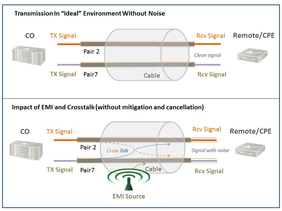
Overcoming Crosstalk Actelis Networks

Pdf Suppression Of Near And Far End Crosstalk By Linear Pre And Post Filtering

Next Near End Crosstalk Troubleshooting And Testing Fluke Networks
Https Www Jpier Org Download 19043004 Pdf

Difference Between 2 Types Of Crosstalk Near End Crosstalk Next And Far End Crosstalk Fext Home

Cabling Guide Fiber Optic Networking Next Fext Elfext Types Of Crosstalk

Crosstalk Or Coupling In High Speed Pcb Design Altium Com

How To Engineer Acceptable Far End Crosstalk Rule Of Thumb 21 Edn
Next Near End Crosstalk Troubleshooting With Dsx Cableanalyzer Fluke Networks
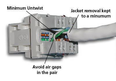
Next Near End Crosstalk Troubleshooting And Testing Fluke Networks
Https Www Newark Com Pdfs Techarticles Megger Structuredcablecertificationtests Pdf
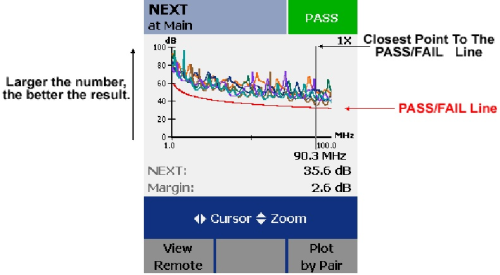
Next Near End Crosstalk Troubleshooting And Testing Fluke Networks
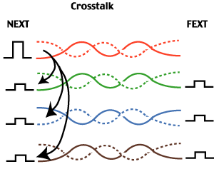
Uncle Ted S Guide To Communications Cabling Testing
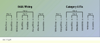
Solving Category 5 Near End Crosstalk Problems Cabling Installation Maintenance
Minimisation Of Crosstalk In Vlsi Routing

Twisted Pair Copper Cabling Ppt Download
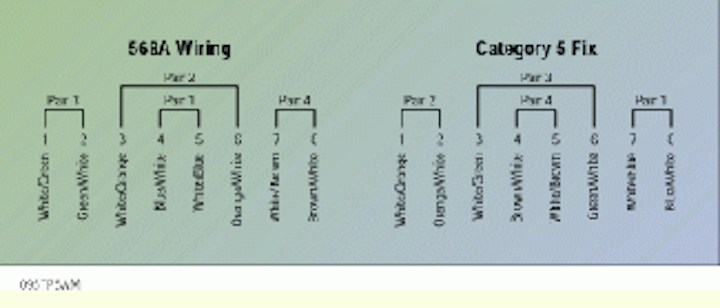
Solving Category 5 Near End Crosstalk Problems Cabling Installation Maintenance

Difference Between 2 Types Of Crosstalk Near End Crosstalk Next And Far End Crosstalk Fext Home

